Certified
ISO 9001:2009
Address
Okhla Industrial Estate Phase 1
Timing
24 x 7
Flooring Radiant Panel Compliance ISO 9239-1, ASTM E648, NFPA 253
Flooring Radiant Panel Compliance ISO 9239-1, ASTM E648, NFPA 253
The Flooring Radiant Panel apparatus is used to determine the critical radiant flux (CRF) of horizontally mounted floor covering systems exposed to a flaming ignition source under a controlled radiant heat environment.
During testing, the specimen is mounted horizontally beneath a gas-fired radiant panel inclined at 30°. This panel produces a defined heat flux gradient along the specimen’s length. A pilot flame is applied to the hotter end of the specimen. The development of any flame front is observed, and its horizontal progression along the specimen is recorded with respect to both time and distance.
In addition, the smoke production during the test is measured by monitoring the light transmission in the exhaust duct.
Regulatory Context
Under the European Construction Products Regulation (CPR), this test method is mandatory across all EU member states for evaluating the reaction to fire performance of flooring materials. It applies to textile floor coverings, cork, wood, rubber, plastics, and other coated flooring products.
The results reflect the performance of the flooring in its tested configuration, including any substrate, adhesive, underlay, or backing. Any modifications in construction or installation may significantly affect the results.
Reported Results
The following parameters are determined and reported:
- Critical Radiant Flux (CRF) or HF-30: expressed in kW/m²
- Flame Spread Distance: expressed in mm
- Smoke Development: reported as the integral of light obscuration (% × min)
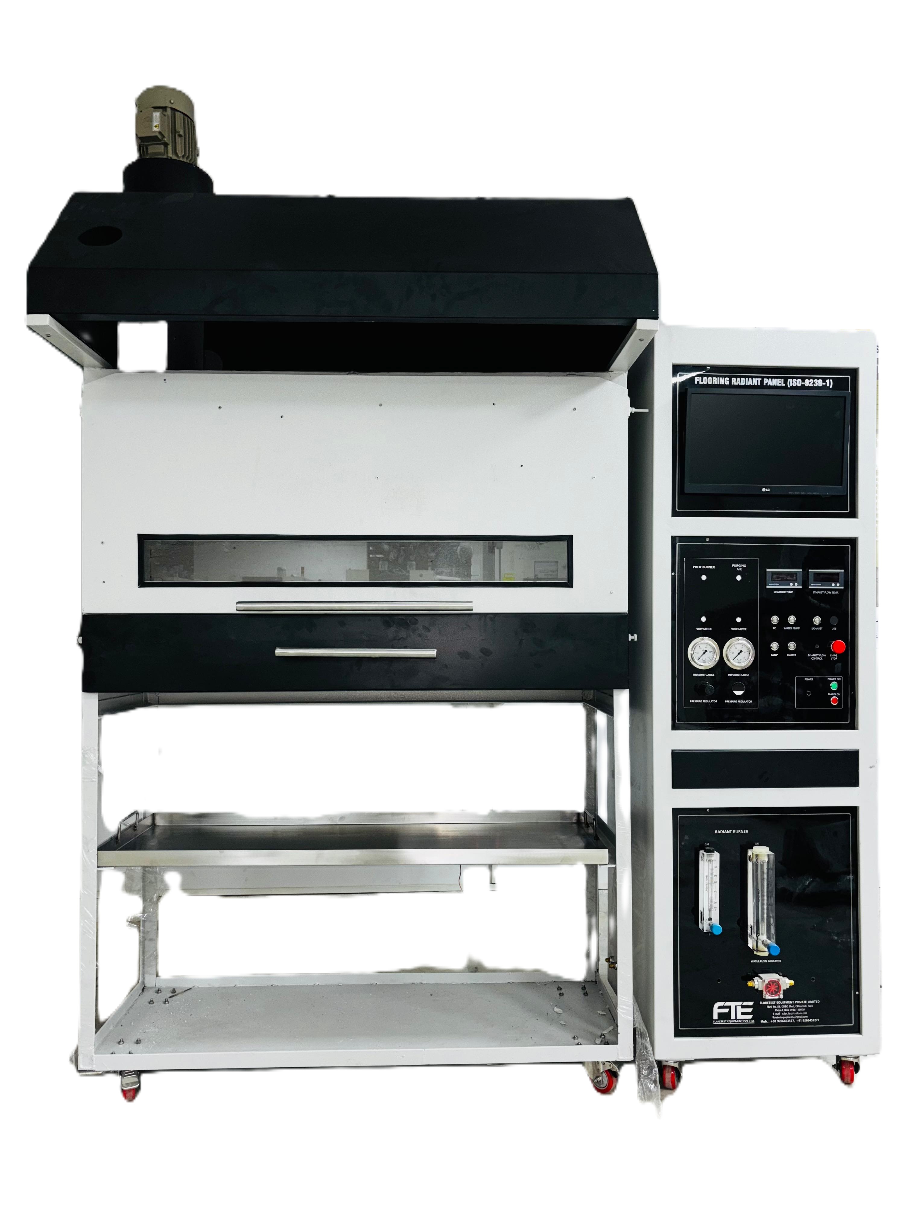
Flooring Radiant Panel (ISO 9239 Compliant)
The Flooring Radiant Panel Test Apparatus is designed to determine the critical radiant flux of horizontally mounted floor covering systems under a controlled radiant heat environment with a flaming ignition source.
Test Chamber
- Constructed of stainless steel with a front-opening door for convenient cleaning and specimen replacement.
- Inner lining consists of a 13 mm thick calcium silicate panel.
- Equipped with a fireproof observation glass (110 mm × 1100 mm), enabling continuous observation of the specimen along its full length.
- Exterior reinforced with a thick stainless steel sheet for durability.
- Below the observation window, a tightly sealed door allows smooth movement of the specimen platform.
- Steel rulers with 50 mm and 10 mm graduations are mounted on both sides of the specimen fixture for flame spread measurement.
Specimen Holder & Platform
- Sliding specimen platform, guided by heat-resistant iron rails for long service life.
- Total air circulation area: 0.23 m², evenly distributed along both long sides of the specimen.
- Specimen holder constructed from 2.0 mm thick, L-shaped, heat-resistant stainless steel.
- Specimen opening: 200 mm × 1015 mm, firmly secured to the platform with two bolts at each end.
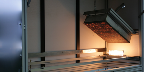
Radiation Heat Source
- Porous ceramic refractory panel in a metal frame, with radiating surface 300 mm × 450 mm.
- Mounted at an angle of 30° ± 1° from horizontal.
- Capable of sustaining >900 °C with a stable, luminous, flame-free radiant output.
Ignition System
- T-shaped stainless steel porous burner:
- Inner Ø: 6 mm, Outer Ø: 10 mm.
- 19 holes (Ø 0.7 mm) along centerline.
- 16 holes (Ø 0.7 mm) at 60° below centerline.
- Cylinder push mechanism applies the pilot flame automatically at a programmed time.
Airflow & Exhaust
- Anemometer: Range 0–10 m/s, accuracy ±0.1 m/s, positioned at 250 ± 10 mm above exhaust chimney centerline.
- Mass flow controller with digital display for flow regulation.
- Frequency converter for blower air volume regulation, with integrated tempering valve ensuring safe, temper-free operation.
- Independent blower with Venturi mixing system for precise air-gas mixture.
Measurement & Calibration
- Infrared Pyrometer:
- Range: 0–800 °C (blackbody temperature).
- Positioned 1.4 m from radiation panel, measuring 250 mm diameter circular area at center.
- Mounted on universal adjustable foundation.
- Water-cooled Heat Flux Meter:
- Range: 0–20 kW/m².
- Built-in cooling, no external water required, zero maintenance.
- Calibration Plate: Stainless steel, 250 mm × 1050 mm, with Ø 26 mm holes at standard positions (110, 210… 910 mm).
- Mobile lifting calibration mode: Heat flux meter can be shifted for convenient calibration, with software plotting standard heat flux curve.
Smoke & Optical System
- Neutral filter: Optical density range 0.05–2.0 (transmittance 89%–1%).
- Light system: 2900 ± 100 K incandescent lamp with silicon photodiode receiver.
- Shutter: Computer-controlled automatic open/close for 0% and 100% calibration.
- Smoke density system: Records transmission curves in real time.
Temperature & Timing
- K-type insulated thermocouple (0–1000 °C) installed in chimney, with software-based real-time display.
- Automatic timer: 1-second accuracy, error <1 second per hour.
Software & Data Acquisition
- Integrated DAQ software records and displays:
- Heat radiation flux,
- Smoke density and transmission curves,
- Air velocity,
- Flame spread distance/time,
- Other test parameters.
- Flame spread recording: Footswitch-enabled, synchronized with automatic computer recording.
- 15″ industrial touch-screen computer for complete monitoring and control of the test.